Drone CAD Overlays & Design Comparisons
See how your construction site compares with the design.
Droneacres can combine current aerial site mapping with supplied CAD drawings or proposed design information, helping project teams visualise the relationship between planned works and actual site conditions.
Prefer to talk it through? Call 07970 393381.


How an overlay works
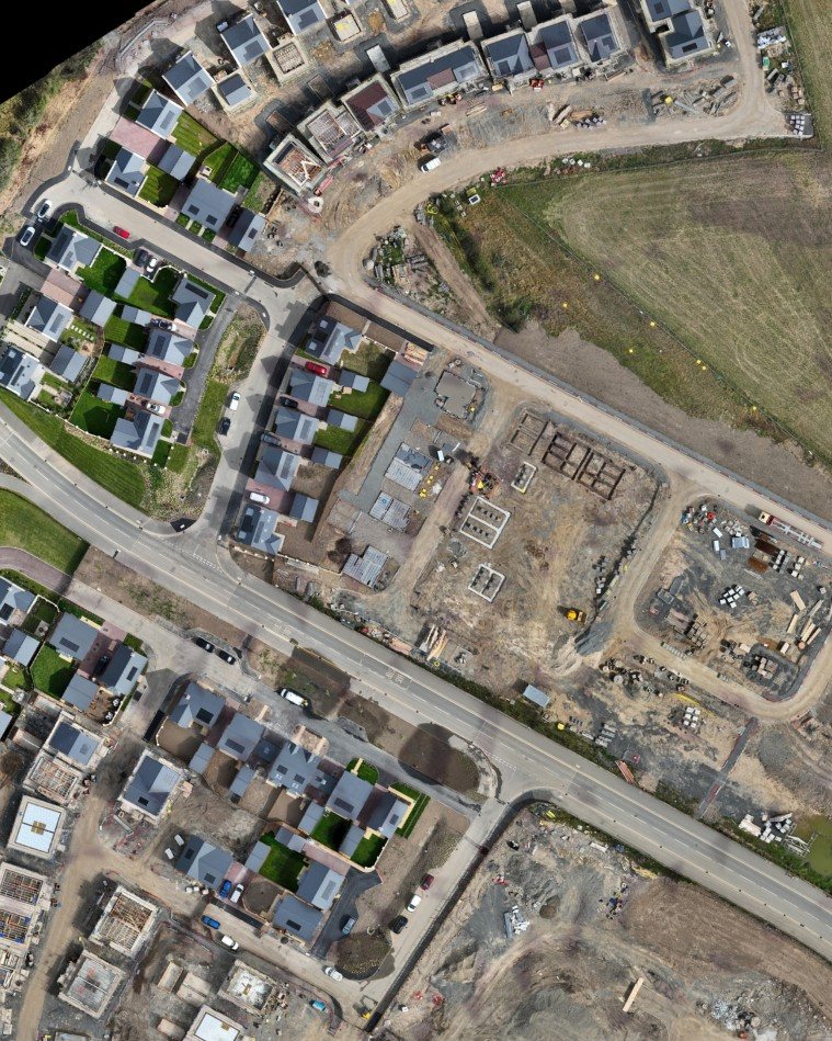
The site is flown and processed into a georeferenced orthomosaic on the same coordinate system as your drawings. Your CAD layout, such as roads, plots, building footprints and drainage, is then placed over the map, so the design and the real site can be seen together.
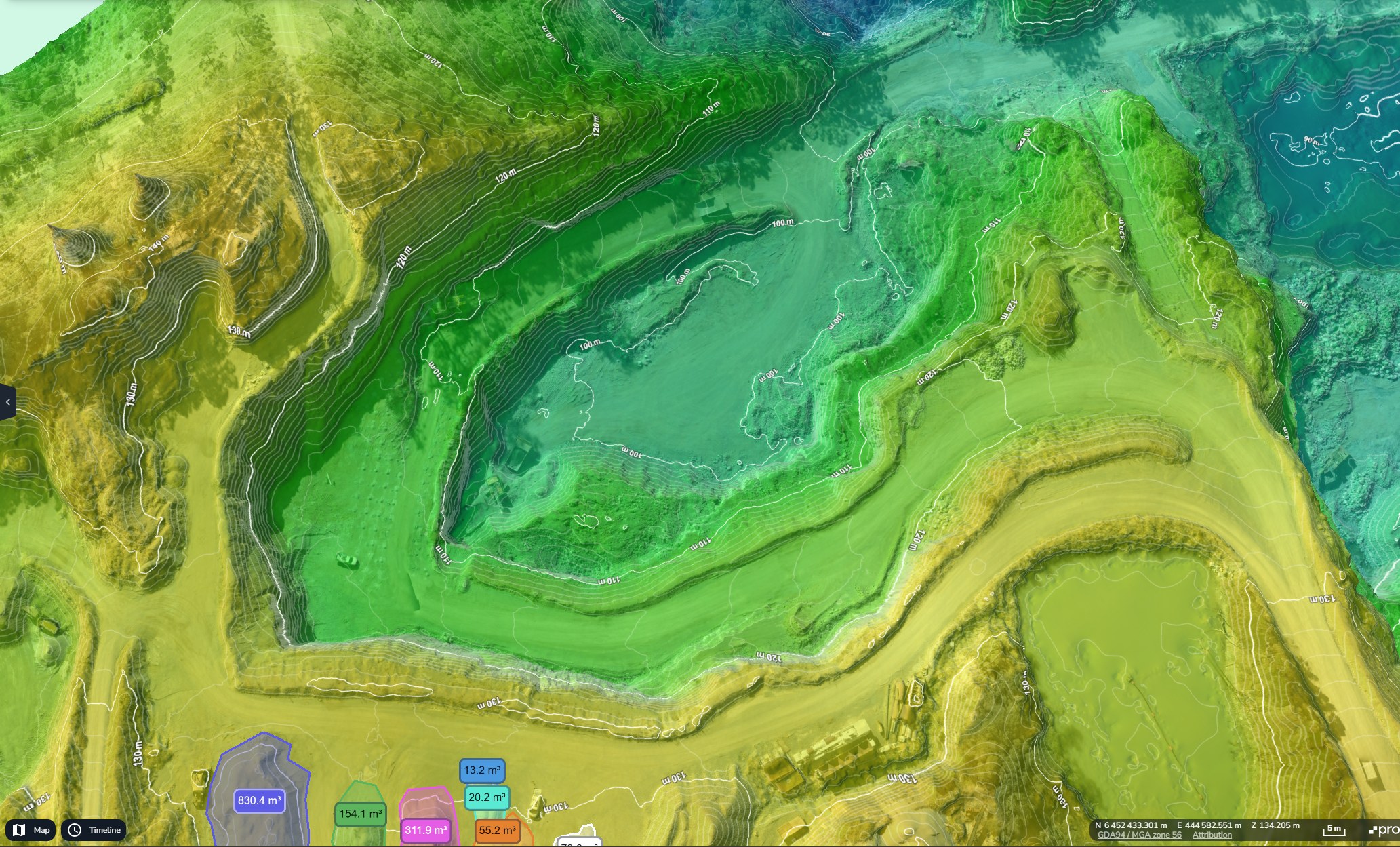
Where you supply a design surface with levels, the surveyed ground can also be compared with it, showing where the site sits above or below design.
Typical uses
- Construction layout visualisation
- Overlaying proposed roads and building footprints
- Comparing site progress against design information
- Understanding spatial relationships on site
- Communicating proposed works to clients and contractors
- Comparing surveyed ground with design levels
Spotting differences
Laid over a current map, differences between the drawing and the site are easy to see, so they can be checked on the ground early.

What you receive
- CAD overlaysPDF, GeoTIFFYour drawings on a georeferenced orthomosaic
- Annotated comparison imagesPDFPoints of interest marked and labelled
- Design against current conditionsPDF, JPEGVisualisations of the design over the site as it is today
- CAD-compatible dataGeoTIFF, ECW, DXFThe orthomosaic and surfaces for your own CAD
- Surface differencesPDF, GeoTIFFLevel differences against a design surface, where supplied
What an overlay is, and is not
An overlay relies on suitable reference information: drawings on a known coordinate system, or enough common points to align them reliably. How the drawings were aligned is recorded with the deliverables.
An overlay is a visual and measured comparison to help your team. It is not an independent engineering compliance certification, and any differences it shows should be checked on site by the responsible engineer.
How the work is done
- DrawingsYou send the DWG or DXF files and explain what needs comparing.
- PlanAirspace checks, a risk assessment and RAMS, with flights agreed around site activity.
- CaptureThe site is flown with ground control and checkpoints on your drawings' coordinate system.
- OverlayThe drawings are aligned with the orthomosaic and points of interest are marked.
- DeliverOverlay images, annotated comparisons and data files in the formats your team uses.
Accuracy and alignment
The orthomosaic is controlled with ground control points and independent checkpoints measured with GNSS, and the checkpoint results are reported. If your drawings are on a site grid or another local system, we work on that system.
Where drawings are not georeferenced, alignment depends on the common points available, and that limits how closely positions can be compared.
What affects the result
- Whether drawings share the survey's coordinate system
- Checkpoint results for the orthomosaic
- Features hidden by plant, materials or vegetation
- Image resolution, set by flight height
Frequently asked questions
What drawing formats can you use?
DWG and DXF are preferred. Other formats can often be converted, so send what you have and we will confirm.
Do you need georeferenced CAD files?
It is best if they are, because the overlay can then be placed directly. Drawings on a local site grid also work if the grid can be related to survey control on site. Drawings without coordinates can sometimes be aligned using common points, with the method recorded.
Can existing site conditions be compared with proposed levels?
Yes, if you supply design levels as a surface, 3D linework or contours. The surveyed ground is compared with the design and the differences are shown as a colour-coded map.
Cut and fill surveysCan overlays be updated throughout a project?
Yes. Repeat visits use the same flight plan and control, so overlays can be updated at key stages of the build.
Construction progress monitoringRelated services
All services